An astronaut is inside a cylindrical capsule with flat ends halfway between Earth and Mars. This capsule is made of stainless steel 5 millimeters thick, 1 meter in diameter, and 2 meters in length. The astronaut is estimated to emit 95 watts of heat to the air inside the capsule, which is at sea-level density of 1.225 kilograms per cubic meter. It is assumed the heat transfer coefficient between the steel cylinder and internal air is 4 watts per meter sq. per kelvin. Will they survive?
To answer this question I created a finite element model in MATLAB. As with any finite element code you must first mesh the geometry. Meshing consists of discretizing the geometry into a set of points, called nodes, that are connected to each other. It is also important for these nodes to be organized in a consistent manner so that neighboring nodes can be easily found. Once the geometry is meshed the heat transfer calculations can be performed and a solution for temperature distribution of the cylinder and temperature of the air can be found, answering the question if the astronaut will survive.
Meshing
All meshing will be with no thickness, it is assumed that because the walls are so thin the temperature difference from the outside of the wall to inside is negligible. To begin meshing I started with the base of the cylinder. The base of the cylinder is just a circle, and will be subdivided radially as well as circumferentially. From trigonometry a point on a circle of known radius R, and angle theta, is:
![]()
Iterating for n number of radial divisions and m number of circumferential divisions an array of nodes can be generated describing the bottom plate. This iteration will start from a single point, and then work its way outward to the final radius of the cylinder. The normal vector to each node will be important as well, but will be explained later.
% Generate Bottom Cap Nodes
n = 3; % Number of radial divisions
m = 20; % Number of circumferential divisions

bottomCapNodes = repmat(struct('Position',[0;0;0],'Normal',[0;0;0],'Temperature',0), n, m); % Initialize array of nodes
for i = 0:n
    radius = cylinderDiameter/2/n * i;
    for j = 1:m
        angle = 2*pi/m * (j-1); % j-1 so that I begin at angle 0

        node.Position = radius * [cos(angle); sin(angle); 0];
        node.Normal = [0; 0; -1];
        node.Temperature = T0;

        bottomCapNodes(i+1,j) = node; % i+1 for one-based indexing
        clear node;
    end
end
Next I generated the length section of the cylinder. Just as before I will iterate circumferentially, but now instead of radially I will iterate along length. The normal will be equal to the unit vector from the center of the cylinder at length L to the point on the circle.
% Generate Length Nodes
n = 10; % Number of length divisions
m = 20; % Number of circumferential divisions

lengthNodes = repmat(struct('Position',[0;0;0],'Normal',[0;0;0],'Temperature',0), n, m); % Initialize array of nodes
for i = 0:n
    length = cylinderLength/n * i;
    for j = 1:m
        angle = 2*pi/m * (j-1); % j-1 so that I begin at angle 0

        node.Position = cylinderDiameter/2 * [cos(angle); sin(angle); 0] + [0; 0; length];
        node.Normal = node.Position;
        node.Normal(3) = 0;
        node.Normal = node.Normal / norm(node.Normal);
        node.Temperature = T0;

        lengthNodes(i+1,j) = node;
        clear node;
    end
end
Finally the top cap nodes can be generated just as before with the bottom cap nodes. This time however the Z position will be equal to the length of the cylinder and I will instead iterate from the outside radius to a single point in the center.
Once all nodes are found I need to combine them into a single mesh, taking care to remove any overlapping nodes. Where the top and bottom caps meet the length portion of the cylinder there will be overlapping nodes, assuming that the circumferential divisions for both the bottom cap and length section are equal which is easy to enforce with code. Given that both have equal circumferential divisions I can ignore the final i column of the bottom cap nodes and just use the nodes created from the length section of the cylinder. Similarly for the top cap nodes I can ignore the first i column and just use the final i column of the length section of the cylinder.
% Total Node Mesh
nodes = repmat(struct('Position',[0;0;0],'Normal',[0;0;0],'Temperature',0), size(bottomCapNodes,1) + size(lengthNodes,1) + size(topCapNodes,1) - 2, m);
nodes(1:size(bottomCapNodes,1)-1,:) = bottomCapNodes(1:end-1,:);
nodes( size(bottomCapNodes,1) : (size(bottomCapNodes,1)-1)+size(lengthNodes,1),:) = lengthNodes(:,:);
nodes( size(bottomCapNodes,1)+size(lengthNodes,1) : end, : ) = topCapNodes(end-1:-1:1, :);

clear bottomCapNodes topCapNodes lengthNodes;
Now I have a clean structured mesh with two index’s, I like to think of the i direction as a position from start, at the bottom center, to finish, at the top center, of the cylinder that works its self out radially, then up the length, and the back in radially. Then for each i the j direction represents the circumference at any i. Below are two plots that have their color interpolated based on i and j, one with edges and the other without. This helps visualize how the nodes are organized.
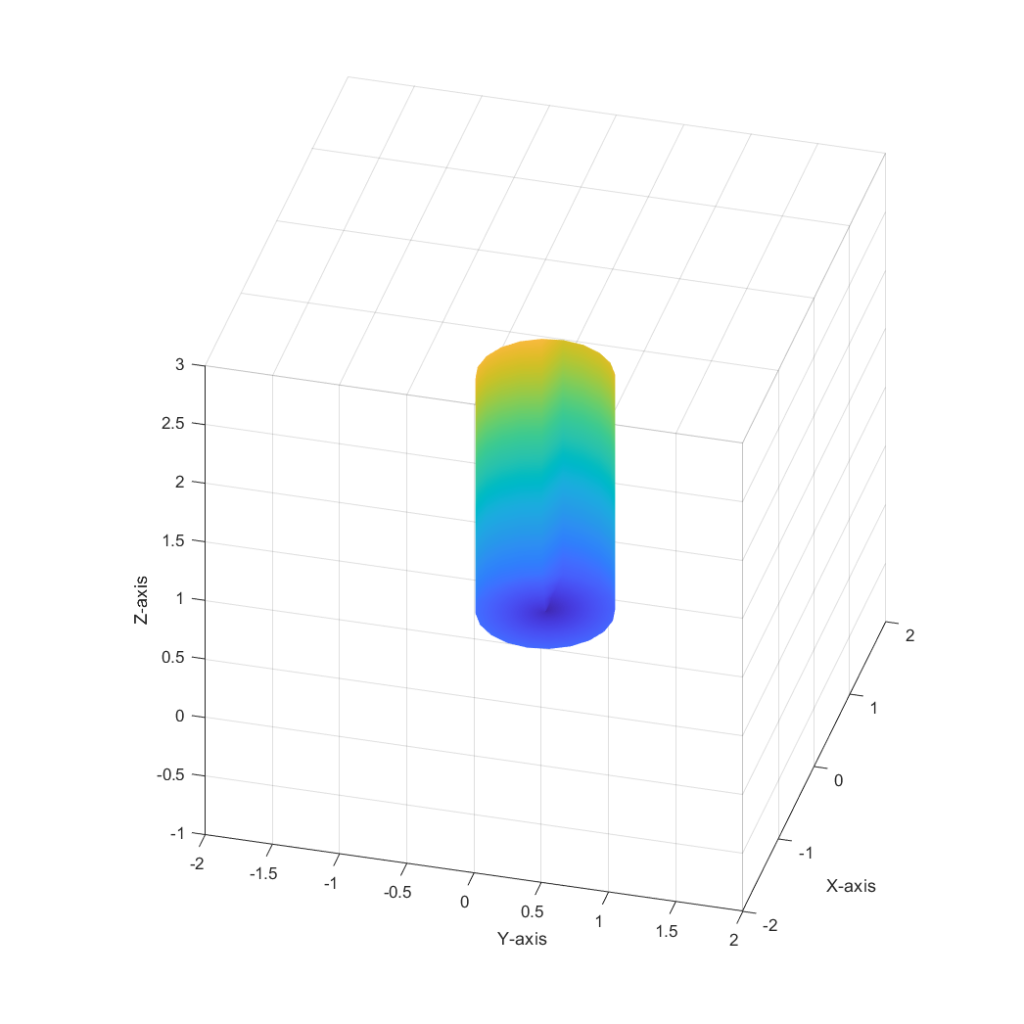
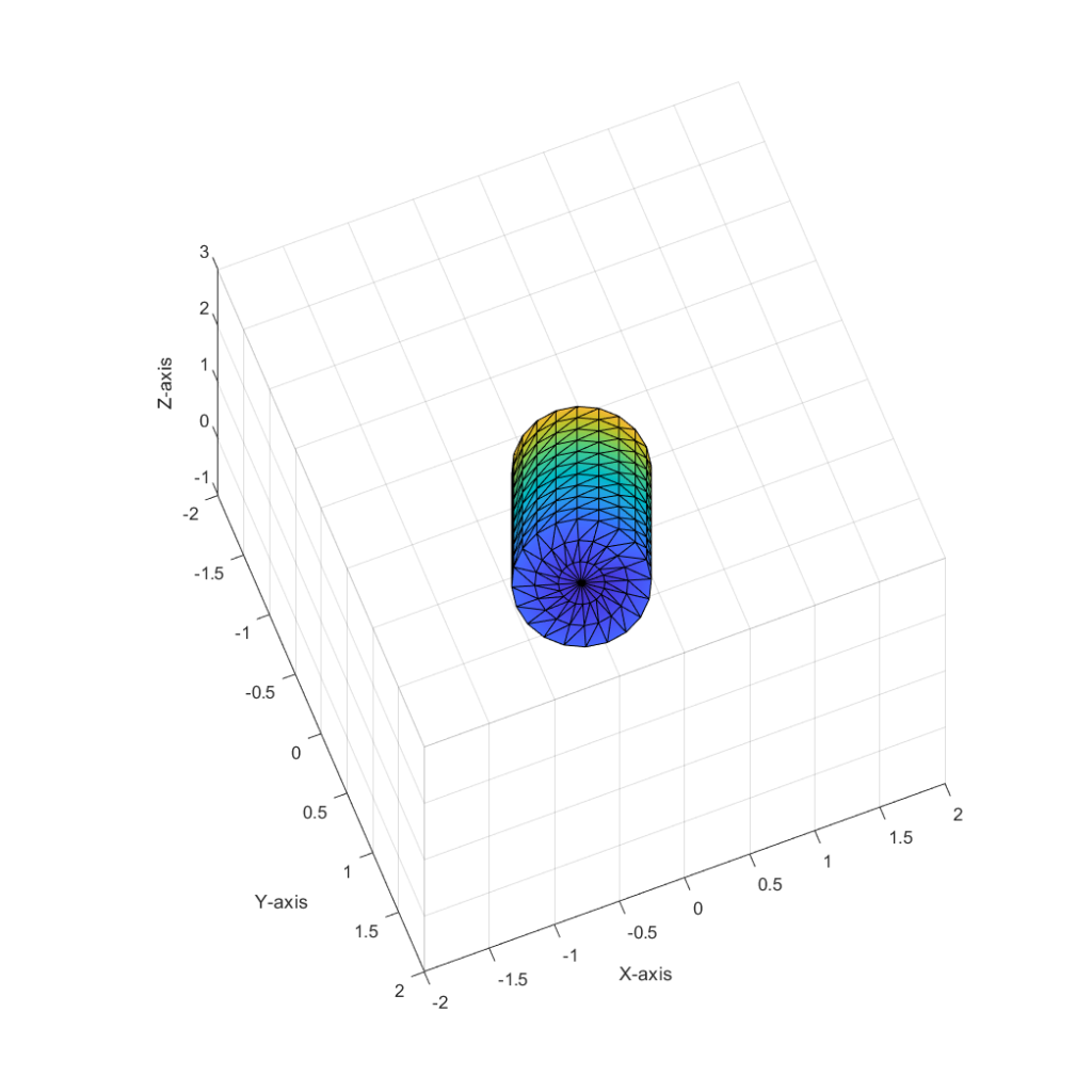
Color is interpolated from dark blue to yellow based on i and j for each node.
Heat Transfer Model
Now that the mesh is setup I can iterate every node and calculate the amount heat transfer. To quantify the heat transfer I start with the first law of thermodynamics:
![]()
The work term can be ignored since no work is being performed on or by the system. Replacing the energy term with the heat capacity of an object:
![]()
The heat transfer term at any node is going to be a combination of solar flux (radiation from sun), black body emission, convective heat transfer with the air, and conduction with the four surrounding nodes.

k is the thermal conductivity, Acs is the cross sectional area of conduction, T is temperature, σ is the Stefan-Boltzmann constant, As is the exposed surface area to solar radiation and convection with air, εIR is the infrared emissivity, α is the solar absorptivity, qsun is the solar flux at the cylinder, and Φn,ij is the angle between the surface normal and incoming solar radiation.
I used the following properties in my analysis. For stainless steel I sourced parameters from a NASA Technical Report document and matweb.com.
| Property | Value |
|---|---|
| α | 0.44 |
| εIR | 0.10 |
| k | 19.43 [W/m/K] |
| c | 500 [J/kg/K] |
| σ | 5.67 x 10⁻⁸ [W/m2/K4] |
The distance x between nodes is approximated as the 3 dimensional distance instead of the distance in each coordinate direction. qsun is calculated using the inverse square law based on nominal Earth solar flux, it is around 850 W/m2. Acs is estimated as the thickness of the steel multiplied by distance between the two nodes of interest. As is estimated as the area surrounding the node of interest, this is nominally a rectangle, except when dealing with the caps or corners where it is instead portions of a circle of a combination of a portion of a circle and rectangle.
In addition to the heat transfer of the cylinder, the heat transfer of the air must also be considered. It is simply the sum of convection heat transfer from all nodes as well as the 95 watts emitted from the astronaut.
![]()
Transient Analysis
Finally to find the steady state temperature dQ/dt is divided by the terms on the right hand side of the equation and then multiplied by some small delta-t. Iterating through time with a small enough delta t will result in a numerical integration that predicts the steady state temperature distribution of the cylinder and the air within.
Results
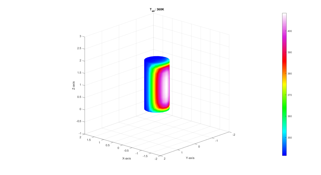
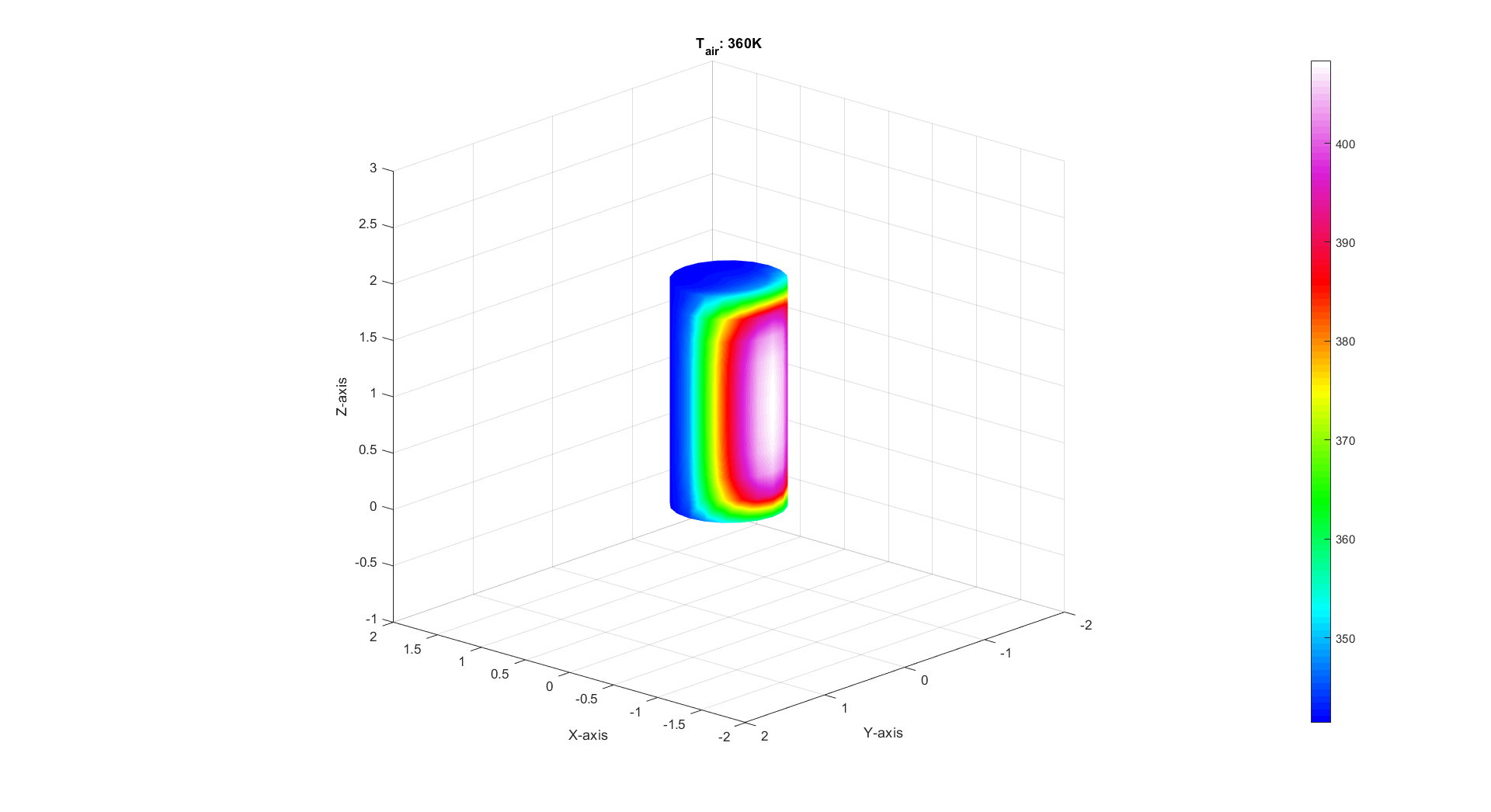
After steady-state is achieved the air inside the cylinder reaches 360K. The steel reaches a peak temperature at the center of the cylinder of 408K, and a minimum temperature on each cap of 341K. This astronaut will most certainly not survive the trip.
