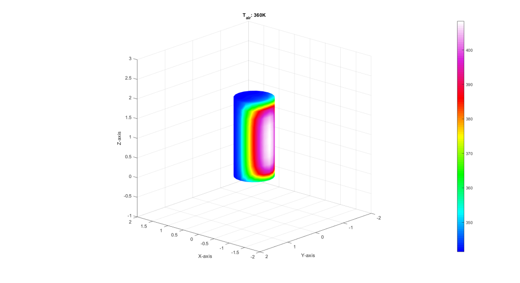
In order to understand the internal loads of an aircraft or rocket fuselage, it is necessary to understand the mass distribution of the vehicle and use the inertial load to estimate accurate shear, bending, and axial forces.
Traditionally static analysis is completed by summing the forces and moments on a beam equal to zero, solving the external reactions, and then drawing shear and bending moment diagrams. However, a fuselage in flight has no external reactions. Instead we use Newton’s second law including the inertial term, but instead treat the inertial load as another applied force in a static analysis.
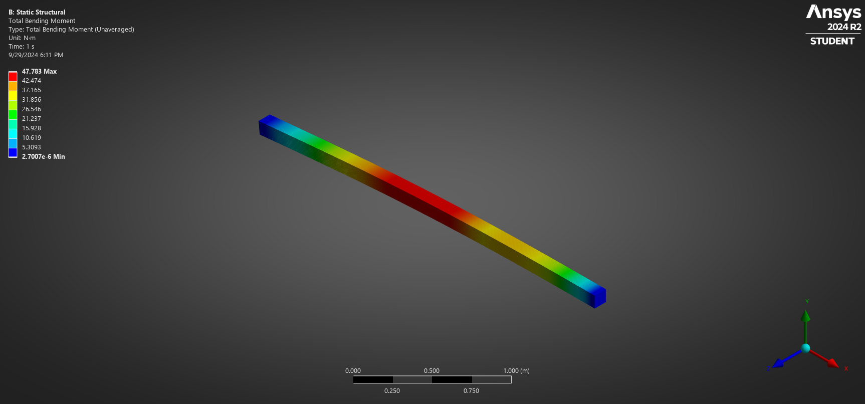
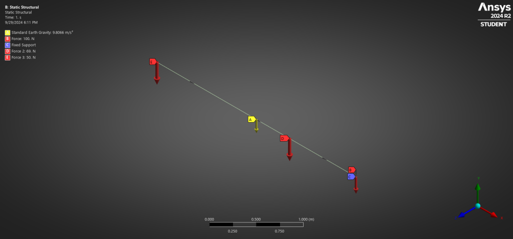
Above is a sample I created to understand this problem without the complexities of a full vehicle. I also created an equivalent beam model in ANSYS Mechanical using Inertia Relief to obtain the static solution to compare my hand calculations. The beam is 3 meters long, with a cross section of 10cm x 10cm, and a linear density of ![]() .
.
To account for the inertial load its first necessary to quantify the rigid body acceleration of the structure.![]()
![]()
![]()
As expected the beam will have a rigidbody acceleration in the negative Y direction. The next step is to properly apply the inertial load to the beam to create a static model that can be analyzed for shear and bending. The inertia load must satisfy equilibrium by balancing net forces and moments applied to the vehicle.
![]()
![]()
![]()
![]()
We know the mass of the beam is uniformly distributed, so at first glance you might suspect the inertial load to be a uniform distributed load of magnitude ![]() , this solution satisfies translational equilibrium, but it does NOT satisfy moment equilibrium because the net moment would act at the CG and be unable to provide the necessary
, this solution satisfies translational equilibrium, but it does NOT satisfy moment equilibrium because the net moment would act at the CG and be unable to provide the necessary ![]() . This is shown in the figure below.
. This is shown in the figure below.
To derive the correct inertia distribution we must satisfy translational equilibrium in addition to moment equilibrium with our added inertial force distribution. First we must recall that inertia is defined as the product of mass with acceleration. For this particular problem the mass distribution is uniform, i.e, mass per unit length is constant. However, we cannot say the same about acceleration. The entire system moves as a rigidbody with a linear acceleration, but it is also rotating, so we must account calculate the additional linear acceleration each part of the beam feels.
![]()
![]() where
where ![]() is the rigidbody rotational acceleration, and
is the rigidbody rotational acceleration, and ![]() is the moment arm measured from the center of gravity.
is the moment arm measured from the center of gravity.
Using this distribution results in a beam with the following applied loads:
Plotting the shear, moment, and bending diagram for the loading condition:
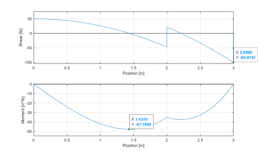
Comparing with ANSYS Mechanical model with inertia relief:
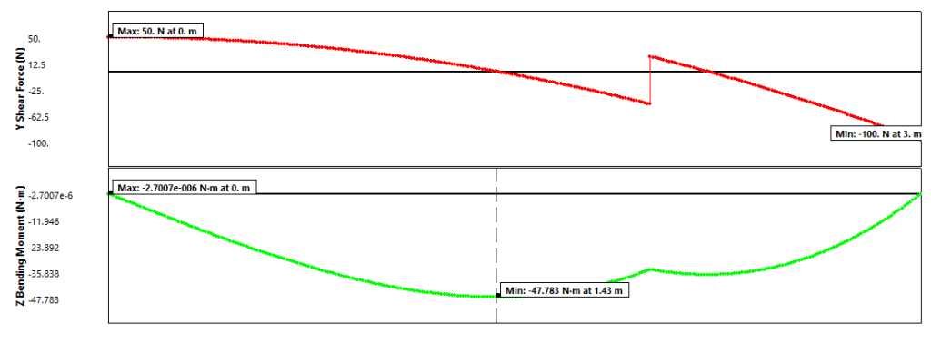
Thus, an exact solution has been found.
